According to Beyond Discovery:
In the horizontal belt or band filter, shown in Figure 7.15, an endless belt arranged in the horizontal plane and running over pulleys at about 0.05 m/s at the feed and discharge ends (similar to the horizontal band conveyor). The principle is applied in the Landskrona band filter, as described by Parrish and Ogilvie^29) . In the filtration, washing and drying zones, where the filter medium passes over vacuum boxes, it may be supported on a separate endless belt which also serves as the drainage member and as the valve. This belt can be provided with side walls to contain the feed slurry and wash liquors, or a flat belt can be used in conjunction with rigid static walls, against which the belt slides. Rubber, or similar, wiper blades which drag against the cake surface can be used to isolate the filtration and washing zones from each other. In some designs the belts move continuously, in others the belts are moved along in stages.

- Figure 7.15. Rigid belt filter
The applications of horizontal belt filters are discussed by Blendulf and Bond^30) . A typical filter for dewatering concentrates is shown in Figure 7.16, and it may be noted that this type of equipment is the most expensive per unit area.
")
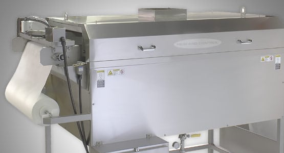
- Figure 7.16. Delkor horizontal belt filter dewatering copper flotation concentrate (filter area 21 m2)
")
An interesting development is the Adpec filter described by Bosley^31) which has an intermittently moving belt. The slurry is fed to one end and the vacuum applied to the underside boxes and filtering occurs with the belt stationary. As the discharge roll at the other end moves inwards it trips the system so that the vacuum is relieved and the belt moved forward, thus avoiding the problem of pulling the belt continuously over the sections under vacuum.
Band filters have several advantages over rotary vacuum filters which are described in the following section. These include:
(a) Some gravitational drainage of liquid occurs because the cake and the belt are vertically separated at all stages of the filtration operation. In addition, a vacuum is not needed to keep the cake in place and this simply supplements the effect of gravity on the flow of filtrate.
(b) Because the feed is from the top, it is not necessary to agitate the suspension in the feed trough.
(c) Large particles in the slurry tend to reach the surface of the filter cloth first and to form a layer which therefore protects the cloth from the blinding effect of the fines, although this does lead to the formation of a non-uniform cake.
(d) Washing is more effective because of the improved structure of the filter cake.
(e) The fitting of an impervious cover over the cake towards its exit will reduce the loss of vacuum due to air flow through cracks in the cake.
- Figure 7.17. Principle of the Pannevis vacuum belt filter

Another development by Pannevis in Holland, shown in Figure 7.17, incorporates vacuum trays which support the filtercloth as it moves at a constant speed which may be varied as necessary. The vacuum tray is evacuated, filtration takes place and the tray is pulled forward by the cloth in such away that cloth and tray move at the same velocity thus offering negligible sealing problems, minimum wear, low driving power requirements and the possibility of high vacuum operation. At the end of the vacuum stroke, the vacuum is released, the tray is vented and pulled back quickly by pneumatic action to its starting position. Although an intermittent vacuum is required, the Pannevis design is in effect a continuous unit since the suspension feed, wash liquor feed and cake discharge are all fully continuous. A vacuum tray is typically 1.4 m long and 150 mm deep and the width and length of the belt are 0.25-3.0 m and 2.8-25 m, respectively.